Introduction of treatment equipment
Accelerator system
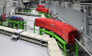
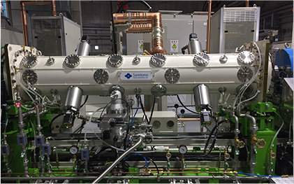
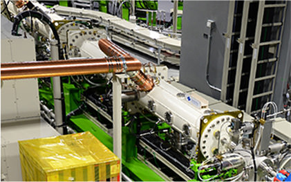
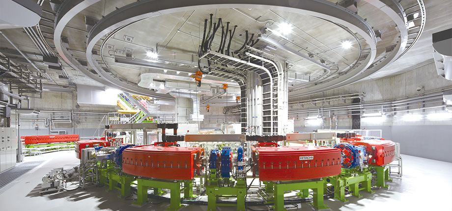 Accelerator room(Synchrotron)
Accelerator is a system that applies high voltage to charged particles and create high-energy charged particles in uniform velocity and direction (=particle beam). For heavy ion therapy, charged particles need to be accelerated to the energy that reaches the tumor. The main accelerator at this facility is a synchrotron (approx. 17 meters in diameter, approx. 57 meters in circumference). This is the most compact heavy ion medical accelerator in the world.
The synchrotron accelerates charged particles to the energy necessary for treatment by using a radio frequency electric field, and these charged particles circulate a few millions of times on the circular orbit (about 57 meters) per second. The maximum velocity of the accelerated particles is about 70% of light speed.
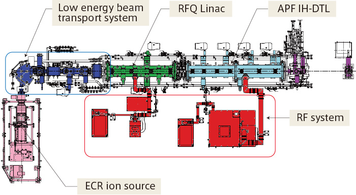
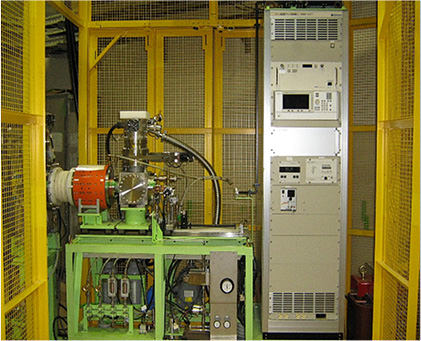
Injector
■Principle and composition of injector
The injector is a device that accelerates the heavy ion beam up to the energy required to enter the synchrotron and consists of an ion source and a linear accelerator.
The ion source creates carbon ion from methane gas. The linear accelerator consists of an RFQ linac and APF IH-DTL, which accelerate carbon ion from methane gas to about 9% of the speed of light by applying high frequency voltage.
Composition of injector
■ECR* ion source
| Method | Permanent magnet ECR ion source |
|---|---|
| Ion source | C4+ |
| Introduction gas | CH4 |
| Energy | 10keV/u |
*Electron Cyclotron Resonance
■RFQ* Linac
| Accelerated ions | C4+ |
|---|---|
| Energy | 600keV/u |
| Frequency | 200MHz |
*Radio Frequency Quadrupole
■APF IH-DTL*
| Accelerated ions | C4+ |
|---|---|
| Energy | 4.0MeV/u |
| Frequency | 200MHz |
*Alternating-Phase-Focused Interdigital H-mode Drift-Tube-Linac
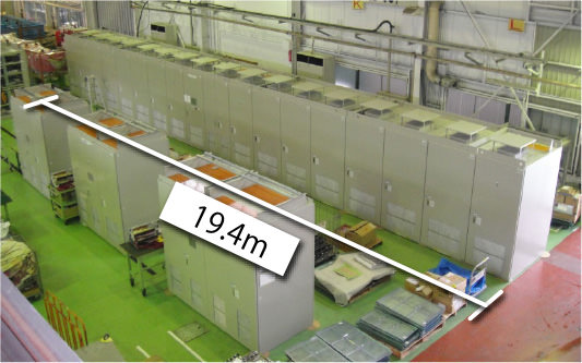
Electromagnet power supply
■About electromagnet power supply
Treatment requires high beam-position accuracy in submillimeter order. In the synchrotron, the accelerated beam is controlled by bending electromagnets that bend a beam along a circular trajectory, quadrupole electromagnets that have a lens role for focusing a beam and steering electromagnets that perform trajectory correction. The electromagnet power supply excites these electromagnets and plays an important role in controlling the beam position accuracy.
■Features of the system and bending electromagnet power supply
This facility, characterized by the compact synchrotron and capability of scanning irradiation as important features, required a stable power supply which can reduce the noise as much as possible, in order to achieve that.
Under the guidance of Prof. Hiroshi Toki, the emeritus professor of Nuclear Physics Research Center at Osaka University, we developed a bending electromagnet power supply that adopts the Sato-Toki symmetrical three-line scheme, which was proposed as the definitive version of noise suppression. The current ripple that represents “fluctuation” shows the lowest value in the world, achieving high beam-position accuracy.
■Bending electromagnet power supply specification
| Output current | 3800A |
|---|---|
| Output voltage | ±1200V |
| Rise | 755ms |
| Fall | 435ms |
| Output average power | 1.8MW |
| Output power | 4.6MWp |
| Received capacity | 2.4MVA(6.0MVAp), power factor 1, measures against harmonic suppression |
| Cooling method | water cooling |
| Electromagnet | 10mH, 8.0mΩ×12series connection |
| Current ripple | 2×10⁻⁶p-p(Flat Top) |
Treatment system
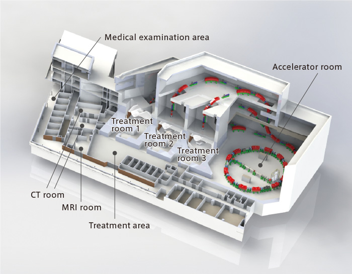
 Treatment room
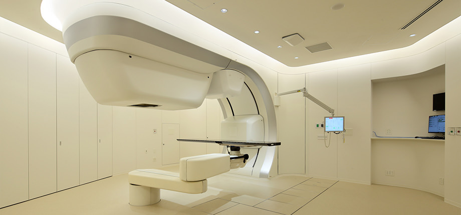
There are 3 treatment rooms in this facility, and the patient position is verified by using the X-ray or the CT simulator before irradiation every time. Treatment room 1 has horizontal and oblique (45 degree) beam ports, and treatment rooms 2 and 3 have horizontal and vertical ports. In addition, treatment rooms 1 and 2 have the Real-time image Gating system, and treatment room 2 has the in-room CT simulator.
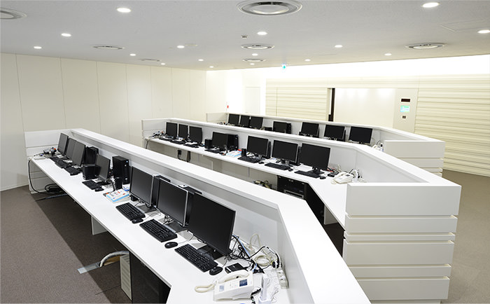 Control room
Treatment room configuration
| Treatment room 1 | Radiation direction (Horizontal / 45 degree) + Real-time image Gating system |
|---|---|
| Treatment room 2 | Radiation direction (Horizontal / Vertical) + Real-time image Gating system + In-room CT |
| Treatment room 3 | Radiation direction (Horizontal / Vertical) |
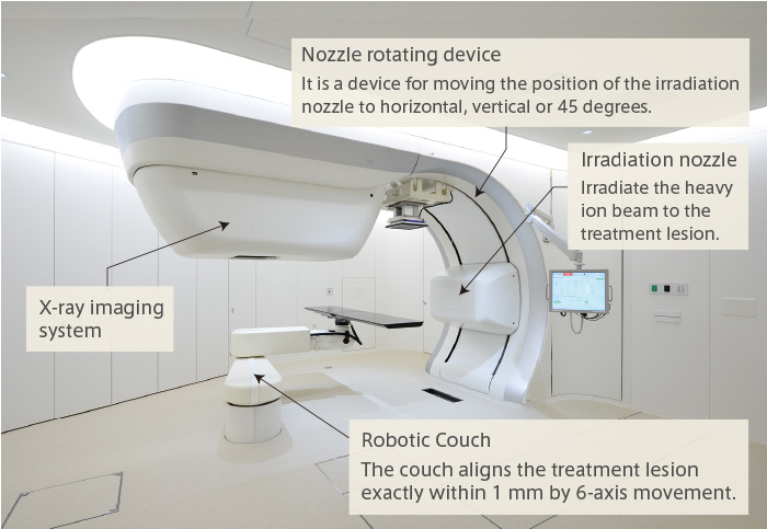
■X-ray imaging system
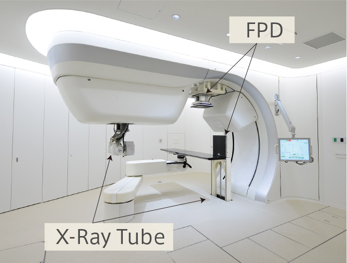 Configuration during X-ray imaging
It consists of an X-ray tube and a Flat Panel Detector (FPD) and takes 2 pairs of X-ray images to determine the treatment lesion. It is stored when not used.
Treatment Planning System
■Function of treatment planning system
The treatment planning system is to simulate and to evaluate the dose, irradiation area and direction of the heavy ion beam before irradiating to the treatment area. It consists of the planning and planning support softwares.
■Planning support software(RayStation Doctor)
The RayStation Doctor, which is adopted as planning support software, is a software for contouring and evaluating treatment planning, and sets contour shapes of tumors on CT images taken in advance.
Configuration of treatment planning system
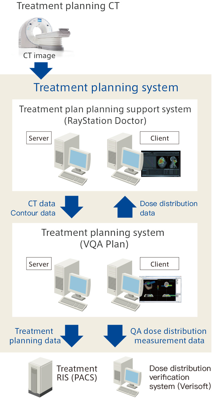
■Planning software(VQA Plan)
The VQA Plan, which is adopted as planning software, is a software that performs irradiation planning and dose calculation. It simulates heavy ion beam dose distribution in the body and creates treatment planning data. The pencil beam method widely used for particle beam is adopted as dose calculation algorithm.
During the treatment period, changes in shape of the tumor can be seen according to the patient's body shape and treatment progress. As VQA has many correcting functions in consideration of patient positioning setup error and organ motion in actual treatment, it is possible to calculate daily dose distribution according to daily change and accumulate daily dose distribution during the treatment period, and doctors can compare the evaluations of the dose distribution with the initial treatment planning and daily dose distribution and the dose integration results by deforming the CT images. Furthermore, millimeter adaptation along with patient's treatment progression can be done quickly.
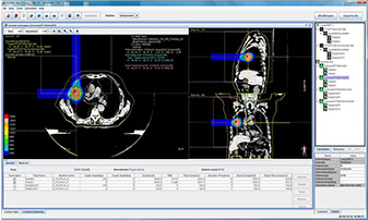 VQA Plan
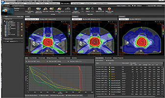 RayStation Doctor
Patient Positioning System
The patient positioning system determines the patient’s position in order to irradiate heavy ion beams with high accuracy. It consists of a treatment couch, laser markers, X-ray imaging devices and a patient image analysis system (PIAS).
■Robotic couch
The robotic couch aligns the patient position with high precision of within 1 mm by 6-axis movement.
■Laser marker
Align the patient's body surface with a laser marker.
■X-ray imaging system (for front and side / for real-time motion tracking)
X-ray imaging system consists of an X-ray tube and an FPD (flat panel detector). Front and side X-ray imaging systems are used to determine the patient irradiation position. For real-time image gating, the position of the gold markers are confirmed in real time by capturing periodic X-ray images.
■Patient Image Analysis System
PIAS (Patient Image Analysis System) calculates the differences between the reference images by the treatment planning system and the current X-ray images of the day of treatment by superimposing the both corresponding images. According to the difference, PIAS also calculates the couch control data automatically which realizes high throughput treatment with minimum operation.
PIAS has three patient positioning methods - DRR*-DR* (2D/2D) mode, CT-DR (3D/2D) mode and CT-CT (3D/3D) mode.
| *DRR | Digitally Reconstructed Radiography |
|---|---|
| *DR | Digital Radiography |
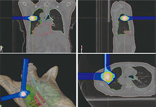
PIAS Patient positioning images
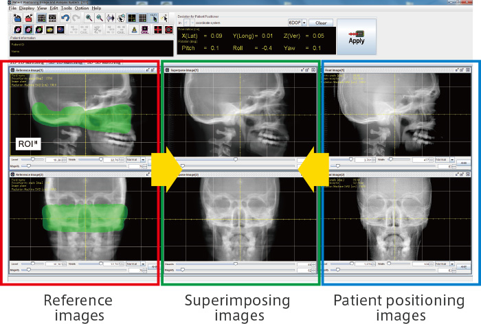
*Region Of Interest
Outline of treatment facilities
Basic specifications of accelerator
| Ion source | Model | Permanent magnet type ECR 1 unit |
|---|---|---|
| Frequency | ~10GHz | |
| Production ion | C4+ | |
| Energy | 10keV/u | |
| Linear accelerator | Equipment configuration | RFQ linear accelerator, IH linear accelerator |
| Frequency | 200MHz | |
| Energy | 600keV/u(RFQ), 4.0 MeV/u(DTL) | |
| Synchrotron | Accelerated ion | C6+ |
| Number of accelerated particles | 5.7×10⁹ ppp | |
| Energy | 140-430 MeV/u | |
| Circumference | 57m | |
| Repetition frequency | About 1/2 Hz (typical value) | |
| RF | 0.97-7.68MHz, 2.5 kV max. | |
| Beam injection | Multiple injection method (effectively 20 turns) | |
| Beam extraction | Slow extraction |
Main specifications of equipment
| Ion species | Carbon ion |
|---|---|
| Depth in the body | Up to 30 cm |
| Irradiation field size | Up to 20 cm × 20 cm |
| Dose rate | 5 Gy (RBE) / min (range 20 cm, irradiation volume 1 liter) |
| Beam delivery system | 3 rooms 6 ports (horizontal 3, vertical 2, oblique 45 degrees 1) |